
Quick Start

This document will help you get your sensor up and running in just three easy steps. For more detailed documentation and additional downloads related to this product, please visit the following pages or access the Download Center
Assembly and commissioning
Prerequisites: For the setup, you will need the sensor, a ConfigBox, a M12 cable attached to a circuit board, a power adapter and a LAN cable. Additionally, you will need a mounting bracket to position the sensor toward your target.
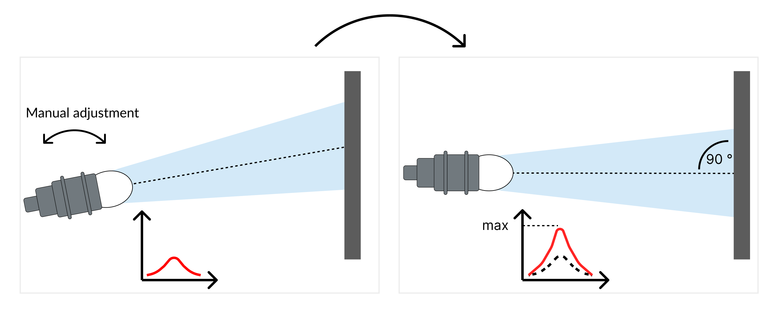
1️⃣ Align the sensor towards the target (rough alignment)
Visually align the sensor so that it is perpendicular to the target. Ensure the mounting allows for fine-tuning of the orientation.
Visite Accessories for mounting equipment.
-20240815-112758.png?inst-v=e1178531-8a08-45dd-b75f-31ac62defc9c)
Visually align the sensor perpendicular to target
2️⃣ Setup configuration box and connect to OndoNet
Connect the sensor to the ConfigBox and your computer as illustrated below. Once connected, enter “config.box” in your browser’s address bar (no “www”). You should be able to open OndoNet within a minute, after connecting the ConfigBox to the power supply.
The configuration box is only required for the initial setup of the sensor for the specific application.
-20240815-112745.png?inst-v=e1178531-8a08-45dd-b75f-31ac62defc9c)
Setup your ConfigBox
Sensor configuration
Prerequisites: Ensure the sensor is roughly aligned to the target, the ConfigBox is connected to your computer and OndoNet is operational. To view measurements and adjust parameters, navigate to the 'Sensor Configuration' section.
1️⃣ Align the sensor towards the target (fine alignment)
Manually adjust the orientation of the sensor while monitoring the signal strength displayed in the configuration software. All detected objects and their signal strength are displayed in the “Spectrum” chart, which is positioned below the “Target” chart.
Align the sensor while monitoring the signal strength
To monitor the signal strength while adjusting the sensor alignment, click on FIX SCALE and ADD HOLD for the magnitude in the spectrum chart. This way you can monitor whether your adjustment leads to an increase or a decrease of the signal strength. Continue until the optimal signal strength is reached.
Once you are done, click on AUTO GAIN in the “Settings” section to further optimize the signal strength. This will automatically adjust the gain parameters of the amplifiers.
2️⃣ Adjust the measuring range
Set the measuring range according to the minimum and maximum distances at which the target should be monitored. Objects detected outside this range will be ignored, enhancing the robustness of the measurements.
3️⃣ Set a signal threshold to suppress unwanted noise
Position the object at the maximum expected distance to set the threshold. The correct threshold value is dependent on the application. However setting the threshold to 20% of the maximal signal strength at the maximum distance is a good starting point.
4️⃣ Configure the sensor outputs (Switching outputs & analog output)
The switching outputs and the current loop (4 - 20 mA) can be configured via the IO Configuration page in the navigation bar on the left.
Switching outputs:
By setting Point 1 and Point 2, you define the distances in mm where the output turns active and inactive; Set Point 2 to the maximum measurement range for Single-Point mode.
Analog output:
You can set the distances in mm at which the current should be 4 mA and 20 mA. The interface will output a current corresponding to the distance of the target. The current will be linear between the two defined distances.
Connecting to PLC
Prerequisites: The Sensor is precisely aligned and Switching outputs/Analog output and parameters are adjusted. Your Sensor is ready to be connected to your PLC. You need an additional open ended M12 8-pin a-coded female cable.
The sensor can now be disconnected from the ConfigBox and used as stand-alone device. All parameters from the previous steps are automatically saved.
1️⃣ Disconnect the sensor from the ConfigBox
Disconnect the sensor from the ConfigBox and connect your M12 8-pin A-coded female open-ended cable to the sensor.
2️⃣ Power up Sensor
To get the sensor running, connect the brown (V+ (24 V)) and blue (V- (GND)) cables to a power source.
3️⃣ Connect Output cables
The grey, yellow and red cables transmit the previously configured switching output signals. Connect the green cable to obtain the analog output.
-20240709-114304.png?inst-v=e1178531-8a08-45dd-b75f-31ac62defc9c)
Electrical connection