
PLC Connection
-20250226-122529.png?inst-v=e8ceedc8-bc75-473d-a79e-d9bf8445a4ea) | To connect the sensor to your PLC, disconnect the ConfigBox from the sensor and connect an open ended M12 8-pin a-coded female cable. Wait with this step until after you finished the sensor configuration. |
Wiring Instructions - General
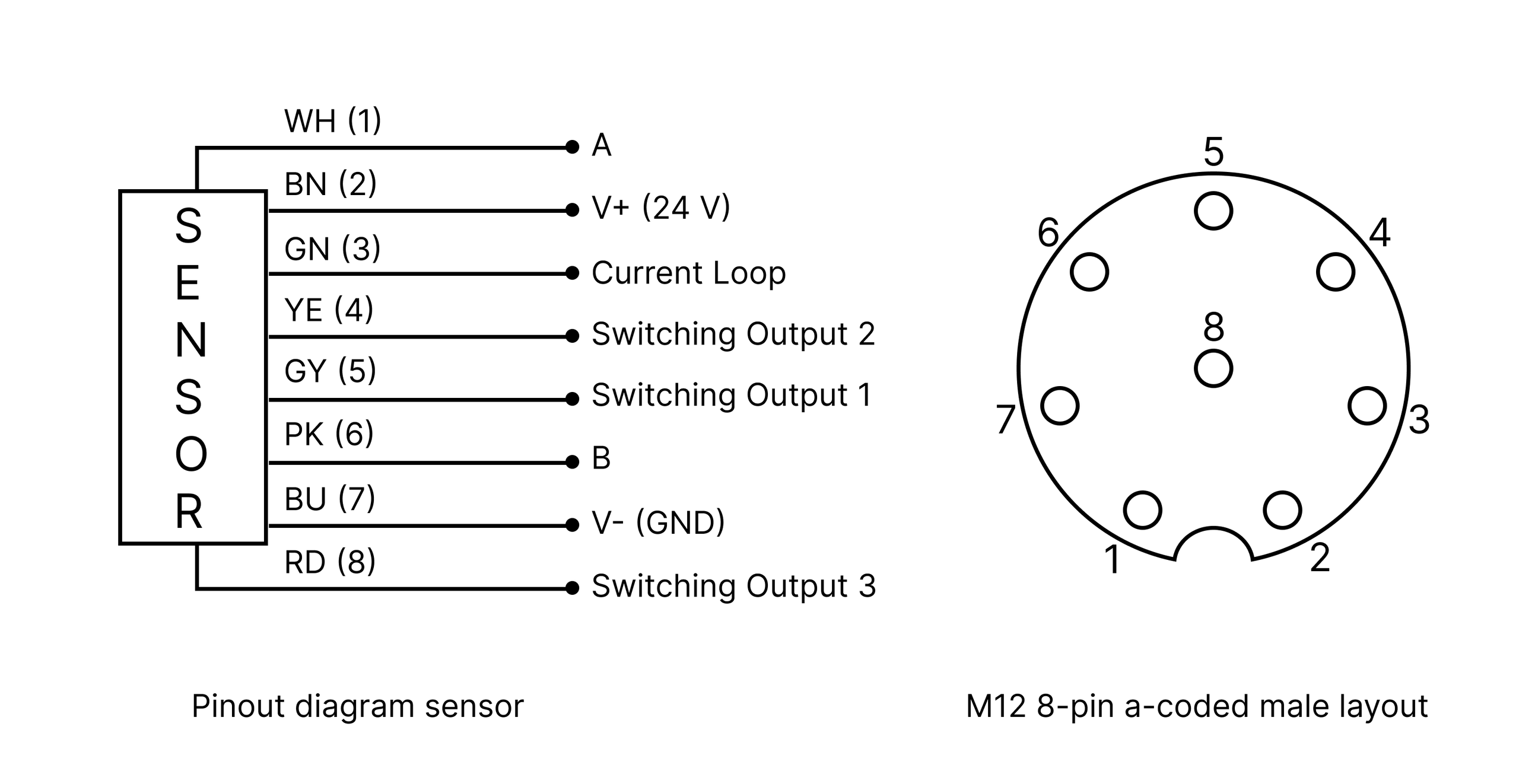
Before connecting the sensor to your PLC, ensure that the sensor is precisely aligned and the switching outputs, analog output, and parameters are properly adjusted. The sensor is now ready to be connected to your PLC. You will need an open-ended M12 8-pin A-coded female cable for this connection. The color code below corresponds to the OndoSense cable. If you use a different cable, the color coding may vary.
| The sensor can be disconnected from the ConfigBox and used as a stand-alone device. All parameters from the previous steps are automatically saved. |
Disconnect the sensor from the ConfigBox:
Disconnect the sensor from the ConfigBox. Ensure that the sensor remains aligned. This will allow the sensor to function correctly once connected to the PLC.
Connect the M12 8-pin A-coded female open-ended cable:
Attach the open-ended M12 8-pin A-coded female cable to the sensor. Make sure the connection is secure to avoid any communication issues between the sensor and the PLC.
Power the sensor:
Connect the brown cable (V+ (24 V)) to the positive terminal of the power source.
Connect the blue cable (V- (GND)) to the ground terminal of the power source.
Ensuring proper power connections is crucial for the sensor to operate correctly.
Digital output - Switching output:
The grey, yellow, and red cables are responsible for transmitting the previously configured switching output signals:
Grey Cable: Connect to the appropriate input on the PLC for the first switching output.
Yellow Cable: Connect to the appropriate input on the PLC for the second switching output.
Red Cable: Connect to the appropriate input on the PLC for the third switching output.
Analog output - Current loop:
The sensor features a 4–20 mA single-ended analog output with 12-bit resolution; connect the green cable to the appropriate PLC input to enable signal reading.
Verify connections and power up:
Power up the system and ensure the sensor is receiving power.
Verify that the PLC is correctly receiving the signals from the sensor.
Wiring Instructions - RS485
The A and B lines represent the RS485 communication interface of the sensor. For proper connection, follow these guidelines:
Using an M12 male open-end D-coded cable:
Connect A, B, GND, and the power cable (24 V) to your PLC to ensure proper sensor operation.
Using an open ended USB/UART adapter:
Connect A, B, and GND via the screw terminal on the ConfigBox connector circuit board (ensure the ConfigBox is disconnected).
For power supply, you can use either the main power input or the screw terminal. Ensure a stable 24 V supply, as some adapter cables only provide 5 V, which is insufficient.
Important notes:
No parallel use with OndoNet: The RS485 lines (A and B) cannot be used while the ConfigBox is plugged into the sensor’s signal connector. During this time, RS485 communication is disabled.
Restoring RS485 communication: After unplugging the ConfigBox from the circuit board, the A and B lines can be used again for RS485 communication.
Baud rate behavior:
When connected to the ConfigBox, the sensor automatically operates at the highest possible baud rate (921600 bps).
This baud rate remains active until the sensor undergoes a power cycle.
After a power cycle, the baud rate resets to the default value of 19200 bps, while all other parameters configured via OndoNet remain intact.
To ensure reliable RS485 communication, confirm the proper wiring of A, B, and GND, and verify the baud rate after power cycles. For more details on RS485 communication, refer to the Application Notes.